Assolombarda undergoes transformation
 by Paolo Micheletti
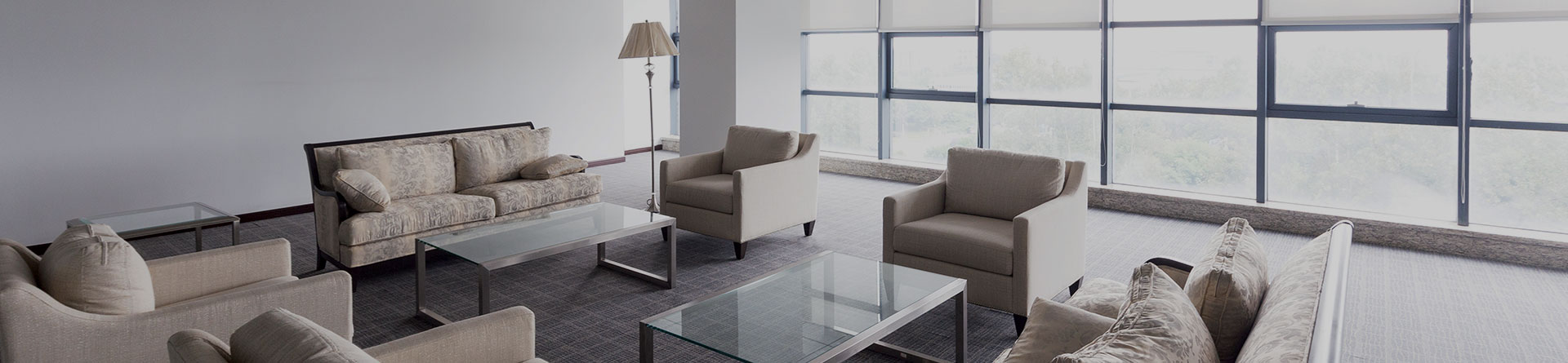
During the revamping of Milan headquarters of Assolombarda, special attention was paid when selecting and designing the wellness systems, not only to achieve thermo-hygrometric conditions but also to control the quality of the ambient air whilst minimising energy consumptions.
The redevelopment project of the Assolombarda headquarters in Via Pantano, Milan, was part of a restructuring process that invested and involved the HVAC systems already installed, in particular the air handling systems, a refrigeration unit and a thermal power station.
The interventions were to be performed without imposing interruptions on office operations and this has restricted the choice of equipment and the VRF heat recovery systems manufactured by Mitsubishi Electric.
Upon completion, primary air and exhaust stale air distribution and treatment systems were also installed.
This was a complex operation that was successfully completed thanks to the accurate planning of interventions and work stages.
The main methodologies adopted and the most important HVAC systems installed are described below.
There was a variety of equipment and plant systems installed on the second basement floor in the Assolombarda building:
Thermal power station.
Centralised refrigerating system consisting of three condensation tower water coolers.
Air conditioning plant with a number of air handling units. There were two types of air handling systems: one which serves specific areas (auditorium, conference rooms and lecture rooms) and one that serves the rest of the building (floors offices and common areas).
Moreover, on the roof (sixth level) there was another utility area with two evaporation towers at the service of the refrigeration unit.
As requested by Assolombarda, we restructured the first floor through to the fifth floor, plus the roof, with partial restructuring of the mezzanine floor and the basement.
The redevelopment project foresaw the upgrading of all existing facilities and construction of new air conditioning systems in the areas subject to intervention.
The restructuring work performed can be summarised as follows:
The four floors, originally scheduled for restructuring (first, second, third, fourth), became five in the executive plan drawn up by the Customer (first, second, third, fourth and fifth), part of the ground floor and part of the basement.
The existing cooling system was obsolete, and due to Assolombarda’s need to relocate the current system from the second basement floor to the roof, it was dismantled and a new one was installed on the roof.
Following a specific request, we also installed cooling systems in the elevator utility rooms to avoid the recurrence of blockages and disruptions of the elevator service due to overheating of equipment in these areas.
Cooling system for the new transformer substation on the second basement floor.
Supervisory, control and management system for all monitored parameters.
The restructuring works were carried out in stages, according to a work schedule drafted by Assolombarda split into the following phases:
Step 1: First floor and second floor
Step 2: Third floor and fourth floor and part of the basement
Step 3: fifth floor, part of the mezzanine floor
Technical area phase: technical area on the roof, utility room on the second basement floor and main technical inspection access. The technical areas were developed gradually in accordance with the foreseen work phases.
The floor-by-floor restructuring was conducted with operational areas (worksites) restricted to work areas. This meant that the areas not subject to restructuring activities were able to continue operating as usual and were available to Assolombarda during the work schedule.
DESIGN CRITERIA
The plant systems were designed to ensure some basic conditions:
- safety and compliance with specific regulations
- reliability and maintenance over time of the investment value
- control flexibility
- environmental well-being
- containment of operating costs and energy consumption.
The main choices applied in order to meet these objectives are outlined below.
Safety
The project choices were based on strict observance of all existing national and European regulations and standards.
The measures taken regarding fire risks were essentially:
- selection of self-extinguishing and flame retardant materials, with low toxic gas emissions when realising the distribution networks, insulation and cladding;
- selection of intrinsically safe equipment, which would not be the primary cause or propagator of fire;
- installation of all the equipment in outdoor technical areas or dedicated utility rooms, segregated by REI 120 partitioning elements from all other areas of the building;
- installation of fire dampers in ducts crossing the REI partitioning elements.
Reliability and maintenance of the investment value over time
The objectives of high reliability and durability of the systems were pursued through the following interventions:
- a plant system supervision centre with preventive maintenance schedule;
- selection of standard equipment produced by firms with well-established presence on international markets, all providing efficient technical assistance services;
- engineering solutions and equipment of high quality and innovative technical content;
- suitable clearance area in the technical plants to ensure full access to the equipment, guaranteeing easy maintenance and in compliance with the instructions provided by the manufacturers of the various components;
- instrumental equipment to guarantee control over the functions of the plant systems and individual equipment, with appropriate connections to the centralised control centre;
- accurate descriptions using technical specifications, of the quality of materials and the methods of installation.
DESCRIPTION OF INTERVENTION
The plant systems which underwent intervention work were mainly the:
- Air conditioning systems
- Air exhaust and/or ventilation for washrooms and ancillary rooms
- thermal regulation systems with field instruments and direct digital control regulating system designed for connection to a supervisory system.
The main plant facility works carried were completed at the same time, in accordance to the work schedule provided by Assolombarda:
- floors from 1 to 5 cooling, heating, primary air distribution and exhaust air expeller systems
- mezzanine floor cooling, heating, primary air distribution and exhaust air expeller systems
- basement cooling, heating, primary air distribution and exhaust air expeller systems
- columns for primary air, air expelling, hot and chilled water pipes, direct expansion circuit columns
- roof ventilation, cooling and primary air distribution systems
- 2nd basement floor modifications to the existing air handling units, new circuits for hot and chilled water, and a primary air humidification circuit
- new refrigeration unit on the roof.
- automatic control system
DESCRIPTION OF PLANT FACILITIES
The basic elements taken into account when selecting the plant facilities proposed for the project were, in detail:
The geometric configuration of the building (dual exposure to sunlight).
The need, reported by Assolombarda, to relocate the refrigeration unit located on the second basement floor.
The architectural restructuring project for the Assolombarda premises (layout, foreseen work stations and utility spaces available).
The need to install a new air handling system to guarantee constant exchange of outdoor fresh air to meet air exchange regulations.
The insufficient capacity of the refrigeration plant to achieve the project environment conditions during the summer following the proposed redevelopment.
Modularity and user flexibility. Possibility for Assolombarda to modify, in the future, the current modular layout without having to restructure the plant facilities.
Respect for the environment with low environmental impact plant proposals (the lowest atmospheric emissions obtainable using the currently available technology) and high degrees of energy efficiency.
Description of the new VRF systems
Our examination of the points above led us to opt for newly constructed VRF heat recovery plant systems comprising 22 outdoor units installed on the roof, each of which were connected by means of appropriate cooling circuits to a number of indoor units installed in the various offices.
A primary air renewal and stale air exhaust system was also installed.
The indoor VRF systems are able to provide or extract heat automatically, room by room; the renewed primary air is channelled to every room at a capacity foreseen by the applicable regulations. The VRF systems selected were built by Mitsubishi Electric.
As the outdoor units are fitted with inverters to control compressor capacity, it is possible, especially in the middle seasons, to cool areas which are subjected to the action of solar radiation and also heat areas, if necessary, on the other side of the building which is not exposed to direct sunlight with maximum energy savings. The flexibility of use is optimised as the supply of hot or cold air is proportional to actual needs. The outdoor units modulate system operations according to requirements. The cooling circuit distribution networks are made from small copper pipes, and the installation led to an appreciably fast execution of works.
The primary air flows from the air-conditioned areas, via insulated channels to the common areas (generally corridors).
An extraction system expels part of the air coming from air-conditioned rooms, extracting it from the rest rooms, the other part flows out of the building naturally due to overpressure.
As mentioned above, the restructuring plan imposed the need to foresee that the new plant system (VRF) and parts of the existing plant system could both operate at the same time.
As the VRF systems do not interact in any manner with the existing cooling and heating plant system, they proved to be the only solution that would allow the possibility of performing contemporarily:
- the floor redevelopment project
- the construction of the new refrigeration plant on the roof and the dismantling of the existing refrigeration plant on the second basement floor
- the construction of the new thermal power plant on the roof and dismantling of the existing plant on the second basement floor
- functionality of the offices during the work-in-progress stages.
The refrigeration plant
Assolombarda had requested the dismantling of the refrigeration plant located on the second basement floor. The new refrigeration plant was installed on the roof in the dedicated utility area.
The new refrigeration plant feeds the new primary air conditioner, also located on the roof, and the existing air handling units located in the technical area on the second basement floor.
The decommissioning of the existing refrigeration plant was only completed after the new refrigeration plant on the roof had been installed.
The chilled water is produced by an air condensation liquid cooler with axial fans for outdoor installation, with semi-hermetic screw compressors which use the R134a refrigerant.
The refrigerator plant was equipped with a partial heat recovery system for summer post-heating of primary air.
Primary air handling and expulsion systems
The setup of the outdoor air handling unit together with the supervision and control system allows users to manage all the controlled parameters (temperature, humidity, indoor air purifying and limitation of noise) with maximum energy savings.
In fact, heat recovery systems have been installed with glycol water fan coils which, depending on outside temperature, can also operate in "free cooling" mode when the conditions (temperature and humidity of the air outside) make it convenient.
The system provides renewal of ambient air with filtration, heating, humidification and post-heating in winter and cooling, dehumidification and post-heating in summer.
The outdoor air intake installation point was identified in a regulatory position and is not influenced by expelled air streams.
An extraction system draws the air from adjacent rooms through transit grilles or equivalent openings in the doors.
Each WC room is fitted an extraction valve connected to the expulsion collector.
The expulsion connector, the valves of each WC unit and a fan on the roof are the type of extraction systems used for the blocks of washrooms superimposed on different floors.
As regards the conditions for the maintenance of the air ducts, they have been structured to allow access from the top of each straight section, or with accessible hatch doors or the disassembly of the curves, all flanged, through the suspended ceiling which is accessible in order to conduct cleaning operations.
Condensation exhaust networks
All indoor units are connected to a high density polyethylene condensation exhaust network. At the foot of each column, and the connections to the various floors, there is an inspection hatch and a sling to aid cleaning interventions on the network.
The connection to the general exhaust network was achieved by installing "constantly wet" siphons.
The exhaust columns are open at the top with an outlet into the atmosphere, to avoid, along with the constantly wet siphons, the possibility of unpleasant odours being channelled into the building.
All networks are equipped with horizontal sub-trims, straps, siphons and inspections at curves and junctions that require it.
Inspections have been planned for the straight sections, one every 15 meters at most, or at least in sufficient numbers to ensure the cleanliness of the networks in case of accidental occlusion.
Supervision and management
PFor installations of new construction is planned integrated supervisory system, consisting of a family of hardware and software modules that together constitute an integrated system of controllers, sensors, actuators, and operator interface devices. These systems allow the supervision, control and management of technological facilities for conditioning, ventilation and heating.
The systems have the ability to integrate various functions necessary to manage the building, thus simplifying the job of operators to ensure comfort.
Control points are provided for each level (concentration) for the management of the environment unit of VRF systems. Each unit operates independently, performing on their own specific controls and alarm management. The failure of a single component or a connection on the network does not stop execution of the functions of control over other equipment.
Substation, located in special cabinets located in the utility area in coverage and technique on the second floor underground, making monitoring and management of components and parameters of the installation of hydronic (primary air handling units, water coolers, electro-pumps, exhausters, thermal stations).
The supervision system allows, in short, the management of controlled parameters (temperature, time etc..) Manned by a local or remote operation from any location (personal computer) of any operator, after entering a password.
The interface between the operator and supervised facilities is therefore a personal computer that allows the control functions, alarm management, control and analysis of the network and data processing.
The software provided minimises their appraisal of the operator through the use of interactive menus, written in clear and the use of standard software applications for PCs. The user interface minimises the use of keyboard and mouse for menu selection pointer.
The user is therefore in a position to send commands to the users or modify a set-point tracking using a mouse on a graphic page.
Varying levels of access are provided to limit the operation of workstations and manipulation of basic data on the basis of the responsibility of each operator.
The system is modular in nature and allows the expansion, with the simple addition of hardware and software applications such as workstations, field controllers, sensors, actuators, etc...