 A dual heat recovery feature characterises the VRF systems installed in three new office buildings: Further to that achieved by the cooling circuit between opposite areas, the exhaust air system feeds the fan coils of the outdoor units, offering an even greater increase in energy-efficiency.
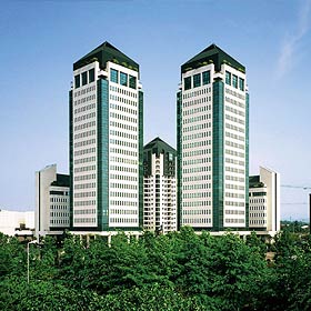
The Torri Bianche Centre in Vimercate is located about 20km north-east of Milan, and just over 6 km from Monza, in the foothills of the Brianza district. This complex is designed to host servicing activities and hotels and residential structures, and has been able to successfully integrate it within the area by offering its users a variety of services, including a shopping mall, restaurants, bars, a multiplex cinema, and a medical centre, to name just a few.
This comprehensive, multi-purpose centre is connected directly to Milan via the east ring-road, and in the future will also be accessible by light rail.
One might say this centre is like an ideal city, which is organised and managed in detail; in fact, it won the Assimpredil "Building the City" prize in 1994.
Nearing completion within this complex are a further three office buildings for high-level offices. The construction company, Giambelli SpA, prioritised the selection of materials, the design of the various spaces, and the choice of air conditioning, security systems, etc.
The company opted exclusively for solutions of the highest quality and lowest environmental impact.
The three new buildings are arranged in a U-shape, around a square created especially for their use, as illustrated in Figure 2; each of these new buildings consists of eight floors above ground, and two basement floors for use as warehouses archives and technical utility rooms. The parking spaces are located in the two basement levels beneath the actual square. The buildings are fundamentally identical. All have a rectangular curtain walled layout, comprising highly specialised windows with high thermal insulation, manufactured by Glaverbel, which are characterised by a K thermal insulation coefficient of 1.1 W/(m2K), incorporating thermal break profiles. The insulating glazing has a depth of 16mm and is filled with argon gas; the insulation on the concrete headers uses sprayed polyurethane foam with plasterboard counter-walls.
The inner partitions are also made of plasterboard, whilst the office floors are made of raised decking covered with carpet/PVC.
Each building has an overall useable surface area of around 6,000 square meters. The standardised floor plan from levels 2 to 6 is open space and can be configured according to user requirements. The entire complex benefits from comprehensive management, which is carried out by the construction company itself.
Gli impianti di climatizzazione
For buildings intended for servicing activities in the office sector, it is very difficult nowadays to accurately design and select HVAC systems, especially because it is not always possible during the initial design and engineering phase to make provisions for the internal heating loads which may arise from any particular usage of the buildings. This in fact may range from normal office use, with modest crowding and fairly moderate sensitive heating loads, to data centres and heavily computerised offices. From a reference standpoint, it is sufficient to examine Table 1 issued by ASHRAE to note the great diversity of unit heating loads (the ‘load factor’) possible, depending on the level of computerisation of the workstations, to understand the difficulties that both the construction company and the HVAC systems designer must respond to. As illustrated in the table, the range of the installed ‘cooling unit’ outputs is between 5.4 and 21.5 W/m2 ; consequently, the cooling power required due to internal loads per workstation must be able to take into account a demand of almost four times the minimum requirement. Table 1 illustrates the values for the computerised equipment alone, these values should be increased for all the other loads present, such as lighting, the people themselves and the required air flow to ventilate the zones.
It is evident that, when faced with uncertainties of this level, the size and choice of the plant system raise some most important questions.
The experience gained by Giambelli over the years, which has its own specialist engineering division within the company that designs HVAC plant systems, achieved positive results using the variable refrigerant flow (VRF) primary air recovery systems produced by Mitsubishi Electric, comprising outdoor units from the PURYP350/400YGMA and PUHYP200/250/YGMA series, which are connected to ducted indoor units, also of various sizes, PEFY-P32/40/50/100VMME, all of which operate with the new refrigerant R- 410A. The air handling units are GUF-100RDH3 type models. The total cooling capacity of the system proved to be 2012.4 kWf; the heat recovery heating capacity was 2259 kWt. In total, 18 outdoor units and 146 indoor units were installed in each building.
| Table 1 – Recommended load factors for various office types | ||
| Office density load |
Load factor |
Office reference features |
| Low | 5,4 | Workstation size 15.5 m2 (6 workstations per 100 m2) with a computer, monitor, printer and fax. |
| Medium | 10,8 | Workstation size 11.6 m2 (8.5 workstations per 100 m2) with a computer, monitor, printer and fax. |
| Medium/High | 16,1 | Workstation size 9.3 m2 (11 workstations per 100 m2) with a computer, monitor, printer and fax. |
| High | 21,5 | Workstation size 7.8 m2 (13 workstations per 100 m2) with a computer, monitor, printer and fax. |
Source: ASHRAE
Two top qualities of the VRF heat recovery systems
These systems highlighted two important qualities in this specific project:
- Great operational flexibility to handle a variety of diverse loads, and therefore the capacity to respond to cooling and heating demands which are most difficult to predict in the project design phase, which results in optimal energy-efficiency and consequently lower management costs. As a result of the high energy-efficiency level of the system, the overall environmental impact of the building is also significantly minimised;
- Its priceless modular features enables installation of additional indoor units compared to those predicted in the original plan, should the cooling capacity required by the user, or the concentration of the loads themselves, exceed those indicated in the design project. For this purpose a greater number of boxed distributors than necessary were included on the cooling lines so that extra indoor units can be connected if the cooling demand becomes significantly higher than normal.
Choosing the VRF heat recovery system was wholly justified given the curtain-walled type construction of the glass surfaces of the three new buildings in addition to the variation of thermal loads throughout the day from solar radiation, consequently, this further enhances the already high energy-efficiency factor of these elite systems. In fact, the search for optimum energy-efficiency within these three buildings did not end here; additional measures were also taken in order to configure the buildings themselves toward a goal of sustainability.
The handling units of the primary air used for ventilation have also been equipped with Lossnay heat recovery units (also produced by Mitsubishi Electric). The feature that has proven to be most significant to the Company in its aim to maximising the energy-efficiency of systems - hence increasing the sustainability of the buildings – was the fact that it installed outdoor units which are powered by the air exhausted from the building, to exploit the enthalpy contents which would otherwise have been released into the atmosphere. The main technical solutions that have been applied are highlighted in Figures 3a and 3b. This shows the exhaust air ducts that terminate in front of the outdoor unit fan coils, incorporating appropriate exhaust nozzles. The outdoor units are, in fact, powered by a combination of outdoor and recirculation air, of which the overall contribution to energy-efficiency is vitally important: during winter, the air that feeds the fan coil is always of a higher temperature than the temperature outside; in contrast, its temperature is always lower in the summer. Both of these circumstances lead to increases in the COP of the plant operational levels.
This measure came up against a series of construction difficulties which were by no means easy to overcome, along with extra economic investment, and by all estimation it can contribute to a further increase in the COP of the systems by at least 15 to 20% throughout the year, both during cooling and heating with the heat pump. Moreover these systems are able to respond, without any deficiency, to the extreme peaks in summer that have now become characteristic of even more temperate climates, such as those in Italy.
Air distribution
The air distribution is ducted and the indoor units are installed near the corridor that runs along the long side of the buildings. The primary air delivery and return air ducts run along the entire length of the building and are fed from a central, vertical upright in the building itself, connected to a handling unit on the roof. The ductwork layout is illustrated in Figure 4. It is also possible to see how each floor plan is divided into two basic zones, facing the two opposite walls. The indoor units are positioned so they can feed the duct branches parallel to the short side for each of the two zones. Each floor is installed with 18 indoor units by standard, each with its own independent settings regime. There are therefore 4 macro zones, two of which are divided into five sub-zones, while the other two, in the section of the building housing the utility blocks, each consist of 4 further sub-zones. The indoor units, housed above the suspended-ceiling, are fed by primary air. Details of the installation of the indoor units are illustrated in Figures 5a and 5b.
Finally, a detail of a coolant distribution box used to connect the refrigerators to the indoor units can be seen in Figure 6.Plant installation management system
A management platform called TG-2000 was used for the system installations in the three new buildings at the Torri Bianche business centre, which represents the highest standard for the entire ‘Melans’ architecture (an acronym for Mitsubishi Electric Air Conditioning Network System). This is characterised by streamlined and scalable architecture, which can adapt to different types and sizes of plant systems, with the capability of effectively controlling up to 2,000 air conditioners.
Figure 5 - Ductworks fed by individual units run along in parallel to the short side of the building, with a comb layout of the floor surface; the photo on the right shows a further detail of the installed indoor units and the primary and recovery air ducts.

Figure 6 - Detail of the installation of a refrigerant distribution box for refrigerant connections to the indoor units.
Figure 7 – A layout diagram of the TG-2000 circuit supervision system serving one of the buildings.
The TG-2000 platform comprises a centralised multiple station system, featuring a multi-tasking operating system with advanced graphics that uses scalability aspects to supervise large widespread and smaller systems, even at a geographical level using an evolved “wide-area” module.
The simple and user-friendly graphic interface of the system guides the user, via interactive icons, through the layout of the building to detect the air-conditioning units already installed as well as various third-party technological equipment connected either to the PLC or to intelligent terminals in the indoor units.
The user selects an icon to view the air conditioner virtual control panel: To simplify matters, the machines can be selected according to predefined groups and zones, and through this function, a command is simultaneously transmitted to multiple utilities.
The TG-2000 software is highly versatile, and designed to enable the use of both standard and specialised functions.
- adjustments to air-conditioning via the virtual control panel
- Daily, weekly and annual timer programming
- The registration of operational data such as alarms, hour counters etc...
- Graphs illustrating trends of variables and consumption, with export data functions
- The collective management of multiple air conditioners.
Where the standard functions guarantee complete management of the operating system, the additional, optional features are used for energy control through:
- The monitoring and distribution of consumptions (Charge), in table and graph formats
- Dynamic control of power consumption (Energy saving/Peak cut).
This feature ensures the system Operator is informed in detail on the building's energy profile and, upon analysing the data made available by the system, can implement energy saving and low consumption strategies.
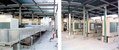
Figure 3a - A general view of the exhaust air duct that feeds the outdoor unit fan coils.
Figure 3b - Details of the duct ends with the air diffusion vents facing the fan coils.
Mitsubishi Electric is completely open to all such concepts so the VRF air-conditioning systems are designed to interact with a variety of some of the most popular communication protocols on the ‘Building Automation’ market.
All the management data recorded directly by the machines and the various controls are made available in standard protocols via a series of interfaces and specific software: LonWorks, Modbus XML and Bacnet used by the main System Integrator within a BMS platform, for global management of the building.
WORK PROJECT PARTICIPANTS
The project design of HVAC systems in the buildings was achieved by:
- Termotechnical Associates Studio, via Che Guevara 4, Reggio Emilia
- The installation of the equipment was undertaken by Adriano Pedrazzoli of Soc Termocal Srl, via Grazzini 14, Milan.
- The Site Manager for the project was Antonio Nicoletti